The issues:
- The problem at hand concerned inadequate cooling of the dolomitic quicklime in a Niems cooler attached to a rotary kiln at a lime plant. The issue was believed to be an uneven air distribution within the stone bed.
- In order to adequately cool the stones and to prevent a surge of hot stones onto the conveyor belt, the plant used unusually large amount of air. The problem was that the excess air resulted in extra secondary air in excess of the kiln requirement and which must be vented via the coal mill off-take. In doing so, the bowl mill air must be diluted and the excess air to the mill must be discarded at a cost.
THE NIEMS COOLER OPERATION
- The cooler is continuously fed from the kiln. However, the cooler discharge is intermittent and set to discharge when it is 60% full and shut off when it is 50% full.
- The duration of the discharge is dependent on the cooler feed rate (or kiln discharge rate) and the cooler discharge rate. The latter is based on the discharge feeder settings which the operator controls.
- The discharge feeder settings vary and are set by the operator in response to the temperature of the quadrant at the discharge. The operator also monitors the belt leading from the discharge for glowing material and adjusts the feeder to ensure cooler material is discharged so as not to damage the belt.
- This arrangement results in the secondary air issue at hand and described above.
AlphaThermal Solution
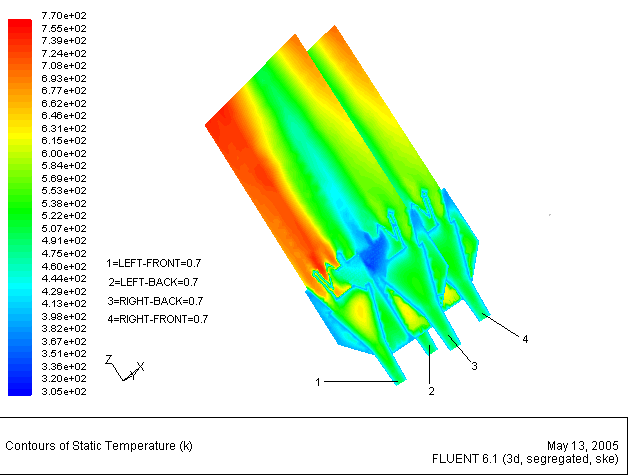
- A mathematical model was formulated by meshing the cooler geometry as having 4 quadrants and a center cone.
- Ambient air is introduced into the quadrants by cooler fans and the surrounding air is forced up through the center core.
- The quicklime fills the quadrants at some height above the quadrants in a uniform pile. Figure 1b shows color coding.
- The system was modeled as an idealized packed bed of stationary material of uniform size and voids with ambient air blown through to cool it.
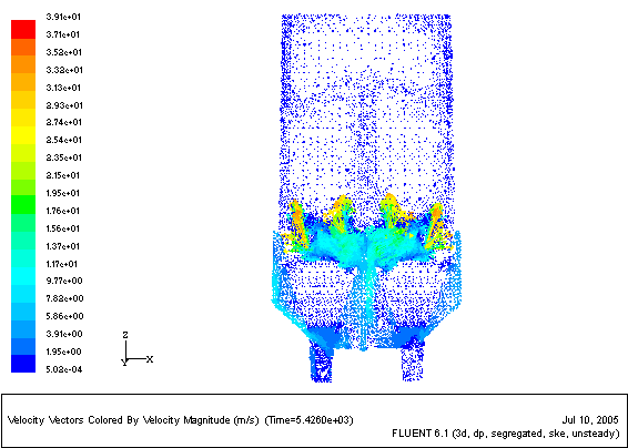
- Velocity and temperature boundary conditions were applied as per the process operational information provided.
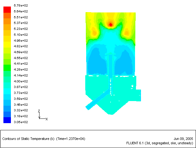
Using a CFD solver, we were able to pinpoint the problem areas and provide a solution to address them. Figures below show velocity and temperature distributions encountered.